Welcome to jeepeasteregg.com Here, we’ve got a detailed guide on the WJ Generation Jeep Grand Cherokee fuse diagram. Check out our handy table below. Spot something off? Let us know, and we’ll sort it out pronto.
Grand Cherokee fuses 1999-2004
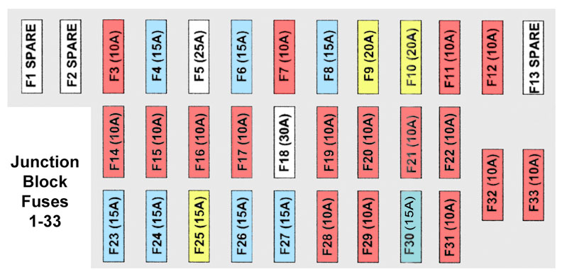
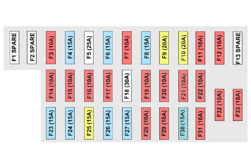
| Cavity | Fuse | Color | Description |
| F1 | — | — | Spare |
| F2 | — | — | Spare |
| F3 | 10 Amp | Red | Headlight high beam left |
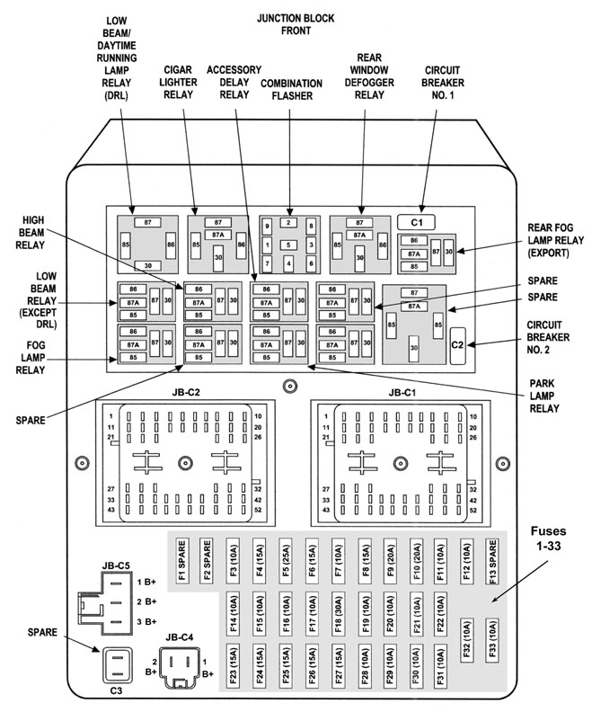
| F4 | 15 Amp | Lt. Blue | Flasher, hazard switch (see Junction Block diagram above for location of turn signal Flasher relay – Mopar p/n 4686094)(Repair tip: WJ flasher repair) Note: On some or all WJ models, this fuse is also used for the ashtray light and the shifter assembly light. |
| F5 | 25 Amp | Natural | Radio amplifier |
| F6 | 15 Amp | Lt. Blue | Park lamps |
| F7 | 10 Amp | Red | Interior lights |
| F8 | 15 Amp | Lt. Blue | Overhead console, rear wiper, IP lights, rear flipper glass solenoid, power locks |
| F9 | 20 Amp | Yellow | Power outlets |
| F10 | 20 Amp | Yellow | Adjustable pedals (2002-2004 only) |
| F11 | 10 Amp | Red | Rear window defrost indicator |
| F12 | 10 Amp | Red | Auto shutdown relay / “Fuel” |
| F13 | — | — | Spare |
| F14 | 10 Amp | Red | Headlight low, left |
| F15 | 10 Amp | Red | Headlight low, right |
| F16 | 10 Amp | Red | Headlight high, right |
| F17 | 10 Amp | Red | Instrument cluster, diagnostic connector |
| F18 | 30 Amp | ? | Trailer tow |
| F19 | 10 Amp | Red | Anti-lock brakes |
| F20 | 10 Amp | Red | Ignition Run / Heated seats / A/C Heater control / Flasher – Left and Right turn signal switch sense |
| F21 | 10 Amp | Red | Ignition Run / Start – PDC (Power Distribution Center) |
| F22 | 10 Amp | Red | Ignition Run / Start |
| F23 | 15 Amp | Lt. Blue | Brake switch |
| F24 | 15 Amp | Lt. Blue | Foglamps |
| F25 | 20 Amp | Yellow | Accessory delay relay (sunroof) |
| F26 | 15 Amp | Lt. Blue | Cigar |
| F27 | 15 Amp | Lt. Blue | Rear fog (export) |
| F28 | 10 Amp | Red | Body Control Module, Acc/Run |
| F29 | 10 Amp | Red | Rear wiper switch. Washer motors |
| F30 | 15 Amp | Lt. Blue | Radio |
| F31 | 10 Amp | Red | Ignition Start |
| F32 | 10 Amp | Red | Ignition Run / Start – Airbag |
| F33 | 10 Amp | Red | Ignition Run / Only – Airbag |
| C1 | 20 Amp | Yellow | Wiper (Circuit Breaker) |
| C2 | 20 Amp | Yellow | Seats (Circuit Breaker) |
| C3 | — | — | Spare |
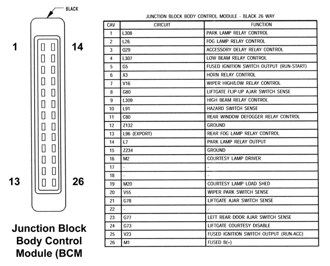
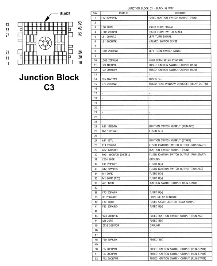
Junction Block Pinouts
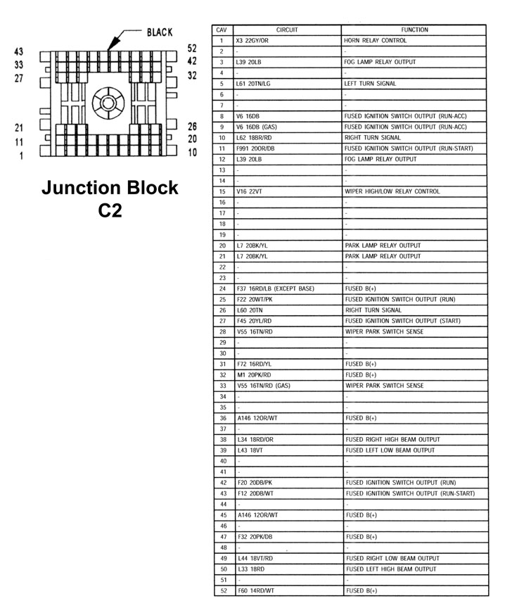
Junction Block C-2
Body Control Module
Junction Block C-3
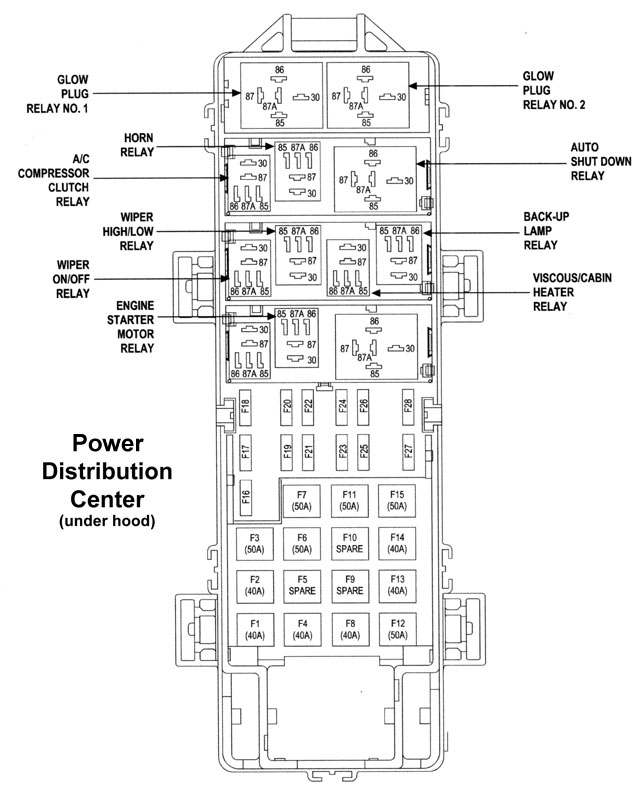
PDC (Power Distribution Center, Under hood)
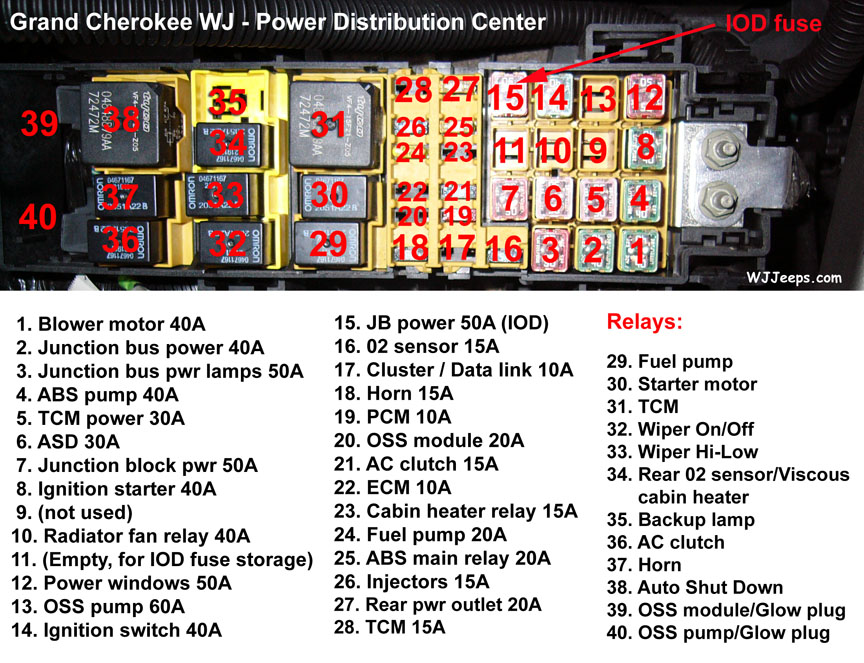
Ignition off draw fuse (IOD) / Vehicle storage
You know when you turn off your car, but it still seems like there’s some battery juice being used up? That’s what we call “ignition-off draw.” It’s totally normal. There’s this thing called the IOD connector that keeps a few gadgets running even when your car’s off, like the clock and some electronic modules. So, don’t worry, it’s just the way things work.
To keep your vehicle’s battery happy during downtime, here’s a simple trick: if you’re storing it for less than three weeks, unplug the IOD connector from slot #15 and pop it into slot #11. This won’t totally zap the battery drain but will definitely help. For a longer nap between three to four weeks, ditch the IOD fuse from the Power Distribution Center (PDC). Now, if your wheels are hibernating for more than a month, it’s time for some serious battery TLC. Disconnect the negative cable and remember to give the battery some love with regular checks and charges. Don’t forget to peek at your service manual for more deets on IOD fuse and battery tips. Keep that battery buzzing, even when your wheels are snoozing.
WJ Flasher Repair Tip
You’ll find the flasher near the fuse box under the dashboard, on the left side of the steering wheel. Check out the diagram at the top for reference. Here’s a handy tip from “tntguy”:
Take a look at the end of the flasher relay where the prongs stick out. You’ll see two plastic tabs holding it together. Gently bend or break those tabs. Then, pull out what’s inside. On one side, you’ll find all the pieces. On the other side, there are some solder joints. Use a magnifying glass to check those joints carefully. You might notice a few with tiny cracks. No biggie! Just put a bit of flux on those cracks and heat them up with a soldering iron until they fuse back together. You might need a little extra solder. Remember to heat up those pins well, not just the solder. Once done, slide the relay back into its cover and secure it with a bit of super glue or tape. And there you have it, good to go.